This Plan Drawing Depicts Arc1720

Plans are a fix of drawings or two-dimensional diagrams used to describe a place or object, or to communicate edifice or fabrication instructions. Commonly plans are drawn or printed on paper, but they tin take the course of a digital file.
Plans are used in a range of fields: architecture, urban planning, landscape architecture, mechanical engineering, civil engineering, industrial engineering to systems applied science.
The term "programme" may casually be used to refer to a single view, canvas, or drawing in a ready of plans. More specifically a plan view is an orthographic project looking down on the object, such equally in a floor plan.
Overview [edit]
Plans are oft for technical purposes such as architecture, engineering, or planning. Their purpose in these disciplines is to accurately and unambiguously capture all the geometric features of a site, building, product or component. Plans can as well be for presentation or orientation purposes, and are often less detailed versions of the former. The end goal of plans is either to portray an existing place or object, or to convey plenty information to allow a builder or manufacturer to realize a design.
The process of producing plans, and the skill of producing them, is often referred to as technical drawing. A working drawing is a blazon of technical drawing, which is part of the documentation needed to build an engineering science product or architecture. Typically in architecture these could include ceremonious drawings, architectural drawings, structural drawings, mechanical drawings, electric drawings, and plumbing drawings. In engineering, these drawings testify all necessary data to manufacture a given object, such as dimensions and angles.
Plan features [edit]
Format [edit]
Plans are often prepared in a "set". The set includes all the information required for the purpose of the set, and may exclude views or projections which are unnecessary. A set of plans can be on standard role-sized paper or on large sheets. It tin can be stapled, folded or rolled equally required. A set up of plans tin too accept the form of a digital file in a proprietary format such as DWG or an substitution file format such equally DXF or PDF.
Plans are ofttimes referred to as "blueprints" or "bluelines". However, the terms are rapidly becoming an anachronism, since these copying methods take generally been superseded by reproduction processes that yield black or multicolour lines on white paper, or by electronic representations of data.
Scale [edit]
Plans are normally "scale drawings", meaning that the plans are drawn at a specific ratio relative to the actual size of the place or object. Various scales may be used for different drawings in a ready. For case, a floor plan may be fatigued at 1:48 (or 1/4"=1'-0") whereas a detailed view may exist drawn at 1:24 (or 1/two"=1'-0"). Site plans are frequently fatigued at one" = 20' (i:240) or 1" = 30' (1:360).
In the metric arrangement the ratios commonly are one:v, 1:10, 1:20, 1:fifty, i:100, 1:200, 1:500, ane:1000, 1:2000 and one:5000
Views and projections [edit]

Symbols used to define whether a projection is either Tertiary Angle (right) or Get-go Angle (left).

Because plans represent three-dimensional objects on a two-dimensional aeroplane, the use of views or projections is crucial to the legibility of plans. Each project is achieved by bold a vantage point from which to encounter the place or object, and a blazon of projection. These projection types are:
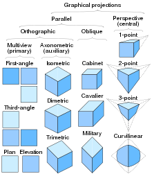
Nomenclature of Plan (drawing) and some 3D projections
- Parallel projection
- Orthographic projection
- Multiview projection, including:
- Plan view or floor program view
- Elevation, usually a side view of an exterior
- Section, a view of the interior at a particular cutting plane
- Axonometric projection, including:
- Isometric projection
- Dimetric project
- Trimetric projection
- Multiview projection, including:
- Oblique projection, and
- Orthographic projection
- Perspective projection, including:
- One-point perspective
- Two-indicate perspective
- Three-point perspective
Planning arroyo [edit]
In that location is no universal standard for canvas order, yet the following describes a common approach:
- General Data : The first sheets in a set up may include notes, assembly descriptions, a rendering of the project, or only the projection championship.
- Site : Site plans, including a primal plan, appear earlier other plans and on smaller projects may be on the first sheet. A project could require a landscape plan, although this can be integrated with the site plan if the drawing remains clear.
- Specific plans : Floor plans, starting with the everyman flooring and ending with the roof plan unremarkably appear most the beginning of the fix. Further, for case, reflected Ceiling Plans (RCP)due south showing ceiling layouts announced after the floor plans.
- Elevations : Starting with the principal, or front end acme, all the building elevations appear later the plans. Smaller residential projects may display the elevations before the plans. Elevation details may appear on the same sheets as the building elevations.
- Sections: Building sections that describe views cutting through the entire edifice appear side by side, followed past wall sections, and so particular sections.
- Details: Details may appear on whatsoever of the previous sheets, or may be nerveless to appear on detail sheets. These details may include construction details that show how the components of the building fit together. These details may also include millwork drawings or other interior details.
- Schedules: Many aspects of a building must be listed as schedules on larger projects. These include schedules for windows, doors, wall or floor finishes, hardware, landscaping elements, rooms, and areas.
Where additional systems are complex and require many details for installation, specialized additional plan drawings may be used, such every bit:
- Structural: While smaller projects may only show structural information on the plans and sections, larger projects accept separate sheets describing the structure of the building.
- Mechanical: Mechanical drawings show plumbing, heating, ventilation and air conditioning systems, or fire protection systems.
- Electrical :Electrical program drawings may include equipment and cable tray layout, lighting and power, grounding, telephone, local surface area network, special communications or betoken systems, or a reflected lighting program.
See too [edit]
- Architectural cartoon
- Blueprint
- Applied science drawing
- Flooring plan
- House plan
- Plat
Source: https://en.wikipedia.org/wiki/Plan_(drawing)
0 Response to "This Plan Drawing Depicts Arc1720"
Post a Comment